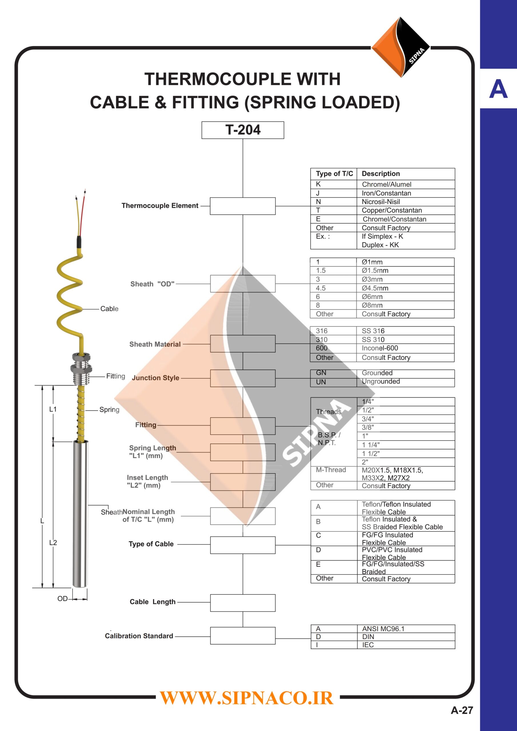
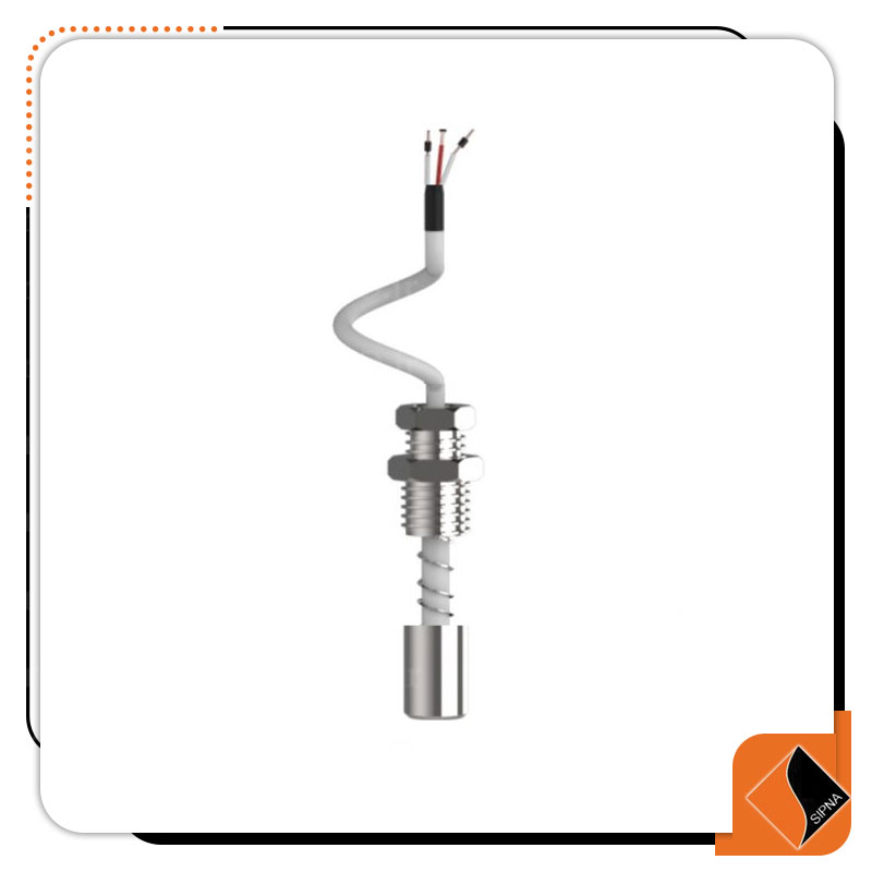
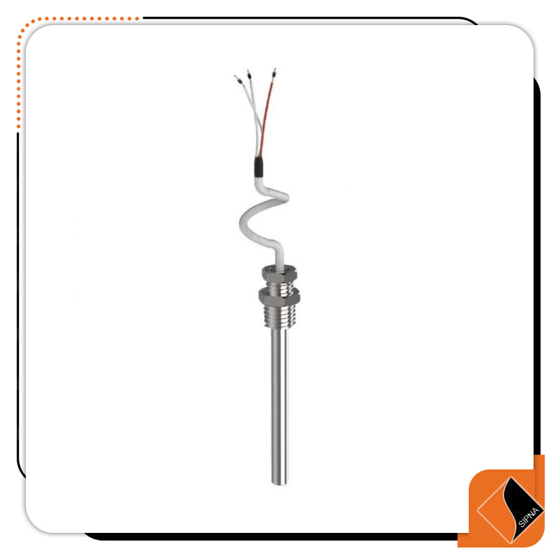
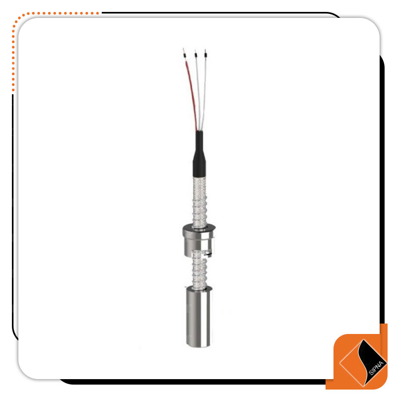
R-204 Series RTD with cable with fitting and spring
R-204 Series RTD with cable with fitting and spring
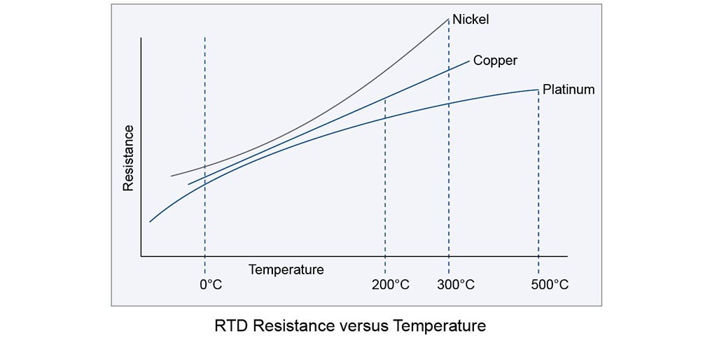
RTDs are temperature sensors that use the resistance / temperature ratio of materials to measure temperature. RTDs have higher accuracy and stability than thermocouples, which are usually in the range below 600 ° C. Resistance temperature sensors are generally made of copper, nickel or platinum, which show a certain resistance at a certain temperature. RTD is an ideal solution if we want to measure temperature with high accuracy, because it has good linear properties over a wide range of temperatures. RTD does not generate output on its own. External electronic devices are used to measure the resistance of a sensor by passing a small current through the sensor to generate voltage. Normally 1 mA or less current flows through them and the voltage across the sensor is measured by the device.
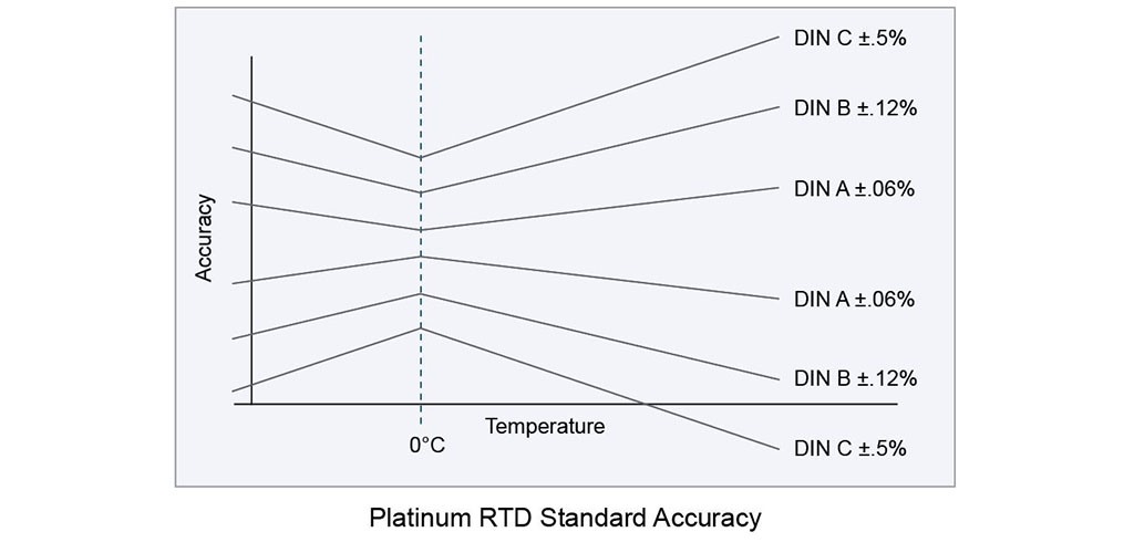
RTDs are made with several standard and bearing curves. The most common standard curve is the ‘DIN’ curve. This curve describes the temperature resistance characteristics of a platinum, 100 ohm sensor, standard tolerances and measurable temperature range.
There are three standard tolerance classes for DIN RTD. These tolerances are defined as follows:
A: ± (0.15 + .002 | T | ° C)
B: ± (0.3 + .005 | T | ° C)
C: ± (1.2 + .005 | T | ° C)

The following curves show the types of RTDs and the ratio of output resistance to temperature tolerance:
 RTD sensors are divided into three general types in terms of the number of output wires:
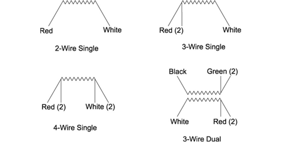
Two wires are commonly used in applications where accuracy is not important. Two-wire configuration makes the simplest measurement technique possible, but suffers from an inherent inaccuracy due to the resistance of the sensor wires. In two-wire configuration, there is no way to directly compensate for the resistance of the wire, which increases the compensation of the resistance measurement.
Three-wire sensors are made with a compensation loop to increase measurement accuracy. With these settings, the controller / measuring device performs two measurements. The first measurement measures the overall resistance of the sensor and the connecting wires. The second measurement is the resistance of the compensation ring. By reducing the resistance of the compensation ring from the total resistance, a net resistance is calculated. Three-wire sensors provide the most common combination in terms of accuracy and comfort. In four-wire sensors, resistance measurements are performed with great accuracy and This method gives the best accuracy, many industrial controllers / measuring devices can not measure the actual four wires. Movable thread means that the thread is not welded to the sheath and wherever the sheath is needed by The wrench is fixed.
Reviews
There are no reviews yet.




Reviews
There are no reviews yet.